

How a Fuel Cell Works
1. Introduction
The Riversimple fuel cell electric vehicle (FCEV) utilises a fuel cell that converts hydrogen and oxygen to water, creating electricity and heat. The electricity then has two possible paths:
- To the four electric motors for motive power.
- To the ultracapacitors for storage and later use.
The key benefit to using a fuel cell is that there are zero tailpipe emissions, except for small quantities of water vapour. This means that a FCEV is locally non-polluting. Therefore, the use of a fuel cell and electric motor(s) represents a clean power-train solution.
2. History
In 1800, British scientists William Nicholson and Anthony Carlisle presented a method for creating hydrogen and oxygen from water [1]. William Grove managed to reverse this process and in 1839 invented the “Gas Voltaic Battery”, in which hydrogen and oxygen was used to create a current. This was effectively the first fuel cell.
In the early 1960s and the following years, NASA became a major contributor to the development of fuel cells. Alkaline fuel cells were the favoured technology for space applications. Alkaline fuel cell technology is now described as outdated [2] and research into other fuel cell technology is now ongoing.
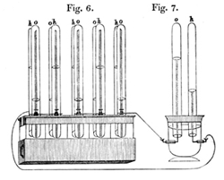
Figure 1 - William Groves Gas Voltaic Battery [1]
3. Types of Fuel Cells
There are many different types of fuel cells, each with respective benefits and drawbacks. A comparison of some of these technologies is shown in Table 1.
Table 1 – Comparison of various fuel cell technologies. [3]
| Type of cell | Temp. Range (ᵒC) | Efficiency Range | Applications |
| Alkali (AFC) | 50 to 250 | 35 to 55% | Spacecraft, possibly land transport |
| Proton Exchange Membrane (PEMFC) | 50 to 100 | 35 to 45% | Vehicle propulsion and micro CHP |
| Phosphoric Acid (PAFC) | ~200 | 40% | CHP plant, ~200 kW units |
| Molten Carbonate (MCFC) | ~650 | >50% | Power and CHP plant, 1 to 2 MW |
| Solid Oxide (SOFC) | 500 to 1000 | >50% | Power and CHP plant, 2 kW to several MW |
NB: CHP = Combined Heat and Power
The fuel cell technology most suited to vehicles is found to be the Proton Exchange Membrane (PEM). The reasons for this are:
- Low operating temperature.
- Ability to vary output quickly to meet power demands.
- High power density.
- Quick startup.
Although the stated efficiency range is 35% to 45%, advances in the technology are continually translating into higher efficiencies; the fuel cells in the Riversimple car have peak efficiencies of 50%. Discussions about the other types of fuel cells will not be found within this document.
4. PEM Fuel Cells
Figure 2 shows a PEM fuel cell which contains flow field plates, an anode, a proton exchange membrane, and a cathode. The main processes involved in a PEM fuel cell are outlined below [4]:
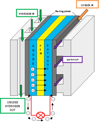
Figure 2 - PEM Fuel Cell
- Pure hydrogen is passed through the flow plates to the anode (negative) on one side of the fuel cell, and oxygen from the air is passed through to the cathode (positive) on the other side of the fuel cell.
- The anode is coated with a platinum catalyst which enables the hydrogen to split into positive hydrogen ions (protons) and negatively charged electrons.
- The PEM allows only the protons to pass through to the cathode. The electrons must then travel along an external circuit to the cathode producing an electrical current.
- At the cathode, the electrons and protons from the hydrogen combine with the oxygen to form water. The water then leaves the cell. This is a continuous process so long as hydrogen and oxygen is supplied.
A single fuel cell will produce approximately 1 V. However, this low electrical potential is of no use in an electric vehicle power-train. Therefore, a number of cells (from 10 to 100 in practice) are connected together in series, separated by electrically-conducting plates. This assembly, as illustrated in Figure 3, is then called a fuel cell stack. The electric potential of each cell is then summed to give the electric potential of the whole stack.
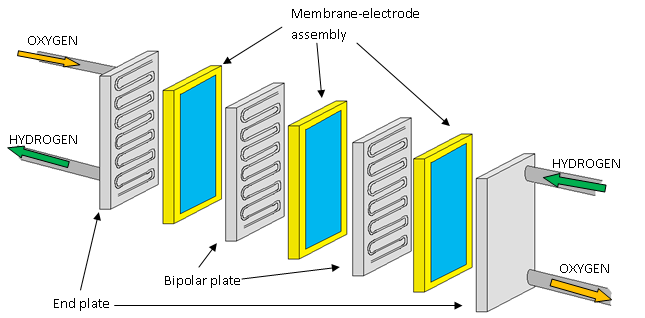
Figure 3 - A Fuel Cell Stack’
The bipolar plates are the electrically-conducting plates which join together the anode of one cell to the cathode of another. The end plates are then connected to the electric circuit and current is allowed to flow.
5. References
[#1] Smithsonian Institute. 2004. Fuel Cell Origins. (online) Available at: [http://americanhistory.si.edu/fuelcells/origins/orig1.htm] (Accessed 13 August 2010)
[#2] NASA. 2005. Fuel Cells: A Better Energy Source for Earth and Space. (online) Available at: [http://www.nasa.gov/centers/glenn/technology/fuel_cells.html] (Accessed 13 August 2010)
[#3] Prof. R.P. Lindstedt and Dr. B. van Wachem. 2009. Third year course in Thermodynamics and Energy, (online via moodle), Imperial College London. Available at: [http://moodlepilot.imperial.ac.uk/mod/resource/view.php?id=2063] (Accessed 13 August 2010)
[#4] U.S. Department of Energy. How Fuel Cells Work. (online) Available at: [http://www.fueleconomy.gov/FEG/fcv_PEM.shtml] (Accessed 13 August 2010)
Written by Simon Vaughan (August 2010)
 Creative Commons Attribution 3.0 Unported License